Authors:
(1) Mohammad Shushtari, Department of Mechanical and Mechatronics Engineering, University of Waterloo ([email protected]);
(2) Julia Foellmer, Mechanics and Ocean Engineering Department, Hamburg University of Technology ([email protected]);
(3) Sanjay Krishna Gouda, Department of Mechanical and Mechatronics Engineering, University of Waterloo and Toronto Rehabilitation Institute (KITE), University Health Network ([email protected]).
Table of Links
Abstract and 1 Introduction
2 Results
2.1 Initial Processed Data for a Representative Participant
2.2 Overall Performance Analysis
2.3 Interaction Portrait Analysis
2.4 Individual Adaptation Strategy
3 Discussion
3.1 Human Adaptation
3.2 Importance of IP Analysis
4 Conclusion
5 Methods
5.1 Feedforward Control Strategies
5.2 Experimental Setup
5.3 Experimental Protocol
5.4 Data Analysis
Declarations
Appendix A Complementary Example Data
Appendix B Comparison with Natural Walking
References
5.1 Feedforward Control Strategies
This section describes three controllers tested in our study.
5.1.1 Time-Based Torque Controller
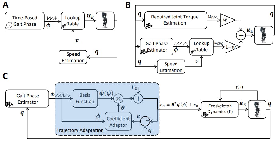
Fig. 8A depicts the block diagram of the Time-Based Torque Controller (TBC). This controller utilizes lookup tables to determine the desired joint torques uE by considering both the gait phase (ϕ(t) and the estimated gait speed (v). To construct the lookup table, measurements of exoskeleton joint torques were taken at different speeds while a participant walked with the exoskeleton governed by a high-gain PD controller. The participant was asked to exert the minimum voluntary effort during walking. The joint trajectories were controlled based on reference trajectories derived from the participant’s walking without the exoskeleton. The input gait phase to the lookup table was obtained by dividing the stride length, calculated using the exoskeleton joint angles (q), by the stride time updated at each heel strike. For this controller, the gait phase (ϕ(t)) was generated based on the desired gait speed, following the formula ϕ(t) = mod(t, T), where T represents the average measured stride time when the participant walked without the exoskeleton at the desired gait speed. For more detailed information about the construction of the lookup table and the gait speed estimator, refer to [26].
5.1.2 Hybrid Torque Controller
Fig. 8B presents the block diagram of the Hybrid Torque Controller (HTC), which combines the torque outputs of two distinct controllers [26]: the Kinematic State Dependent Controller (KSC) and the Gait Phase Dependent Controller (GPC). The KSC incorporates an Artificial Neural Network (ANN) that calculates the required biological torque for the user based on the kinematic measurements of the exoskeleton [27]. On the other hand, the GPC adopts the same structure as the TBC mentioned earlier,
however, instead of relying on a time-based gait phase, it utilizes a real-time estimation of the gait phase derived from the kinematic measurements [28]. The outputs of these two controllers are linearly combined in the HTC: uE = wuKSC + (1−w)uGP C , where w represents the weight assigned to the KSC output.
5.1.3 Adaptive Model-based Torque Control
The Adaptive Model-based Torque Control (AMTC) depicted in Fig. 8C, leverages the estimated dynamics of the exoskeleton to generate joint torques for control. According to [29], the interaction between the Indego exoskeleton and the human in the sagittal plane can be described by the following dynamical model:


/cdn.vox-cdn.com/uploads/chorus_asset/file/25406817/STK051_TIKTOK_CVirginia_B.jpg)


