
Optics 101 for Engineers: How Lenses Secretly Make or Break Your Image Quality
Foreword: Why Image Engineers Should Also Understand Lenses
In the field of image engineering, engineers often invest a significant amount of time and effort in developing and tuning sophisticated Image Signal Processor (ISP) algorithms, striving for the ultimate in color reproduction, noise reduction, and dynamic range. However, a harsh reality remains: no matter how powerful the algorithm, it cannot create something from nothing. If the light information coming from the optical system—the lens—is inherently flawed, then all subsequent digital processing is merely “remedial” rather than “creative” in terms of image quality. The optical system is the first gatekeeper of image quality, yet it is also the most easily overlooked bottleneck.
Consider a common project development scenario: a team might spend months tuning the ISP, hoping to resolve issues of edge softness and color shift. Despite numerous iterations and optimizations of the algorithm, the results consistently fail to meet expectations. Ultimately, upon re-examining the entire system, the root of the problem is often found to be an optical module chosen in the initial stages, which has inherent deficiencies in edge resolution and chromatic aberration performance. Such experiences profoundly reveal that without a high-quality optical foundation, even the most advanced algorithms are like building a skyscraper on quicksand—inefficient and yielding subpar results.
This article will, from an image engineer’s perspective, provide an in-depth yet accessible exploration of how optical systems affect image quality, and explain how the cold, hard data on spec sheets translate into the visible differences in image quality we perceive with our own eyes.
Core Metric 1: Sharpness and Resolution
When evaluating the quality of a lens, “sharpness” and “resolution” are the two most frequently mentioned terms. Resolution refers to the physical ability of a lens to distinguish fine details, while sharpness is the subjective perception of an image’s clarity and definition, influenced by both resolution and contrast. To measure this metric scientifically and quantitatively, one must understand the MTF (Modulation Transfer Function).
Decoding the Lens’s “ID Card”: The MTF Chart
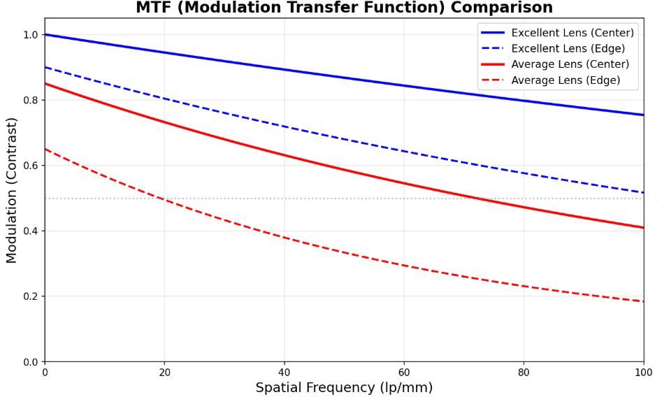
MTF describes a lens’s ability to reproduce the contrast of a scene at different spatial frequencies (levels of detail). In simple terms, it tells us how much of the black-and-white distinctness of a pattern of lines is retained after being imaged by the lens. The horizontal axis of an MTF chart represents Spatial Frequency, measured in lp/mm (line pairs per millimeter), indicating detail from coarse to fine from left to right. The vertical axis represents Modulation, or the ability to reproduce contrast, with 1.0 being perfect reproduction.
An excellent lens will have an MTF curve that is as high and flat as possible, indicating that it maintains good contrast for a wide range of details across the entire frame, from center to edge. Conversely, if the curve drops off quickly, it means the image details will become blurry and indistinct.
The Sweet Spot and the Diffraction Limit
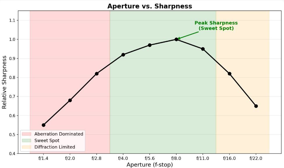
Aperture size also significantly affects sharpness. Many people mistakenly believe that the smaller the aperture, the better the image quality, but this is not entirely true. Every lens has a “Sweet Spot”, typically 2-3 stops down from the maximum aperture (e.g., f/4.0-f/8.0). Within this range, most optical aberrations are effectively controlled, and the lens can achieve its best resolving power. However, when the aperture is stopped down too far (e.g., to f/16 or smaller), the phenomenon of Diffraction becomes significant. Light waves bend around the edges of the aperture blades and interfere with each other, causing the entire image to become softer and limiting the lens’s ultimate resolution.
Common Optical Aberrations – The Algorithm’s Nightmare
An ideal optical system would perfectly converge all light rays from a single point on an object to a single point on the image sensor. In the real world, however, due to the limitations of lens materials and the laws of physics, various optical defects, or “aberrations,” are inevitable. These aberrations are the biggest headache for ISP engineers because they contaminate the image data at its source.
1. Chromatic Aberration
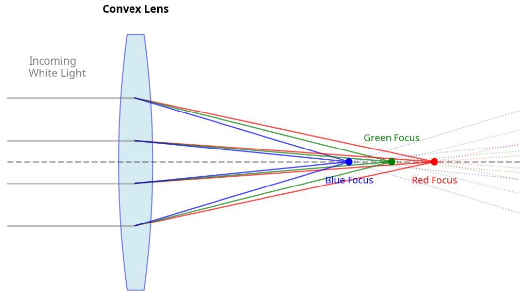
Chromatic aberration arises because the lens material (glass) has a different refractive index for different wavelengths (colors) of light, causing different colors to fail to converge at the same point. This results in annoying “Purple Fringing” or “Green Fringing” at high-contrast edges.
• Axial (Longitudinal) CA: Different colors of light focus at different points along the optical axis.
• al CA: The magnification of the image is different for different colors, causing color fringing at the edges of the frame.
From an ISP perspective, chromatic aberration severely interferes with Color Correction and Demosaicing algorithms. Correction algorithms typically require building a profile based on the lens’s characteristics to perform spatial shifting and scaling of the color channels at the RAW data level. This not only consumes computational resources but also makes it difficult to perfectly eliminate chromatic aberration in all scenarios.
2. Distortion
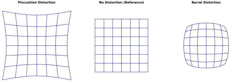
Distortion is the phenomenon where straight lines in the scene are rendered as curved lines in the image. It does not affect the sharpness of the image but does alter the geometry of objects.
• Barrel Distortion: The center of the frame bulges outwards, and straight lines curve outwards. Common in wide-angle lenses.
• Pincushion Distortion: The center of the frame caves inwards, and straight lines curve inwards. Common in telephoto lenses.
For machine vision applications that require precise geometric measurements, or for AI applications that involve object recognition, distortion is a critical flaw. The ISP’s “Lens Correction” module performs a reverse geometric transformation on the image based on a pre-measured lens distortion model. However, this correction process stretches or compresses some pixels, which can lead to a loss of local resolution.
3. Vignetting
Vignetting is the phenomenon where the corners of the image are noticeably darker than the center. Its causes are complex, including physical obstruction (mechanical vignetting) and a natural fall-off in brightness due to the angle of incidence of light (natural vignetting). While sometimes used as an artistic effect, in most applications, it is a defect that needs to be corrected. The ISP’s “Lens Shading Correction (LSC)” algorithm compensates for the brightness of each pixel based on its distance from the center of the frame to achieve a uniformly bright image.

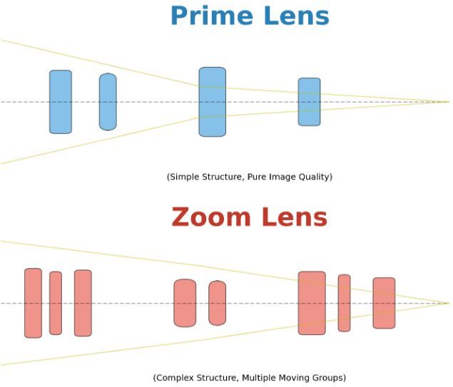
Prime vs. Zoom Lenses: The Trade-off Between Quality and Convenience
From an optical design perspective, a prime lens has a single design goal: to correct aberrations for one specific focal length. Therefore, it can achieve very high image quality with a relatively simple structure and fewer lens elements. In contrast, a zoom lens, in order to be able to form an image at multiple focal lengths, requires complex groups of lens elements to move and compensate, which undoubtedly increases the sources of aberration and the difficulty of correction. Therefore, at the same price point, a prime lens will generally offer superior image quality.
In the development of fixed-lens products like webcams, this point is particularly important. The optical solution for such products must be finalized at the very beginning of the design process. The development team needs to make precise trade-offs between field of view, aperture, distortion control, and cost, based on the product’s target application scenarios (e.g., emphasizing the clarity of a single person in a video call versus needing a wide-angle view for a multi-person conference). Once selected, there is no room for replacement, and all image quality tuning must be performed on this optical foundation. This again confirms the importance of placing optical evaluation at the forefront of the development process.
Conclusion: Incorporate Optics into Your Development Mindset
For any project involving image processing, whether it’s a consumer camera, a professional surveillance system, or a sensor for autonomous driving, it is essential to establish the concept that the optical system is the cornerstone of image quality. Investing sufficient resources in evaluating and selecting the right optical solution at the beginning of a project is far more efficient and effective than investing a great deal of manpower later to remedy an inherently flawed system with algorithms. As image engineers, it is not enough to be proficient in the algorithms of the digital world; one must also understand the principles of optics in the physical world. Only then can one truly master “light” and create exceptional images.
Looking Ahead: In the next article, we will delve into the “decision-making brain” of the camera—the 3A algorithms (Autofocus, Auto Exposure, and Auto White Balance). Stay tuned!


