Table of Links
Abstract and 1 Introduction
2 Unit cell design and analysis
3 Unit cell experimental and numerical characterization
4 Rainbow AM labyrinthine panel
4.1 Panel design and fabrication
4.2 FE model of the AM panel
4.3 AM panel characterization
4.4 AM panel sound absorption results
5 Numerical evaluation of different labyrinthine sound absorption panel solutions
5.1 Macrocell with backing cavity
5.2 Results
Conclusions, Acknowledgements, and References
Appendix I
2 Unit cell design and analysis
In conventional ideal fluid environments, sound propagation is typically described by a lossless wave equation [32–34]. However, when fluids are confined in small regions, like narrow tubes or slits, it becomes necessary to account for structural losses [30,33,34]. There are two primary loss mechanisms: thermal losses, primarily arising from heat diffusion at the boundaries within the sound field, and viscous losses, due to friction with the UC walls. These physical dissipation mechanisms effectively absorb sound energy, leading to perfect absorption when they are balanced by the acoustic energy leakage by radiation from the UC: the matching of the two corresponds to the critical coupling condition [33,35].
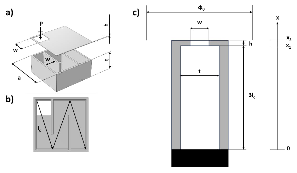
The type of labyrinthine geometry considered in this work (Fig. 1a) is a first-iteration Wunderlich curve [36], which corresponds to a quarter-wave resonator. This design can be studied using narrow tube thermo-viscous loss models to derive its absorption properties. In particular, the designed aperture (Fig. 1a) is responsible both for the losses and energy leakage of the UC, while the cavity (Fig. 1b) is only responsible for the losses. The considered UC can be modelled as a tube with constant cross section 𝑤 × 𝑡, and a rigid backing (Fig. 1c) as pointed out by several works [37–39]. In particular, given the subwavelength size of the system, the equivalent tube can be described as a narrow duct, following the Stinson’s approximation for thermo-viscous losses [40], while the inlet can be studied as a perforated plate using the Johnson-Champoux-Allard (JCA) model, as described in [37].


Authors:
(1) F. Nistri, Department of Applied Science and Technology, Politecnico di Torino, Torino, Italy and Politecnico di Milano, Milano, Italy;
(2) V. H. Kamrul, Politecnico di Milano, Milano, Italy;
(3) L. Bettini, Politecnico di Milano, Milano, Italy;
(4) E. Musso, Politecnico di Milano, Milano, Italy;
(5) D. Piciucco, Politecnico di Milano, Milano, Italy;
(6) M. Zemello, Politecnico di Milano, Milano, Italy;
(7) A.S. Gliozzi, Department of Applied Science and Technology, Politecnico di Torino, Torino, Italy;
(8) A.O. Krushynska, Faculty of Science and Engineering, University of Groningen, Groningen, The Netherlands;
(9) N. M. Pugno, Laboratory for Bioinspired, Bionic, Nano, Meta Materials & Mechanic, University of Trento, Trento, Italy and School of Engineering and Materials Science, Queen Mary University of London, United Kingdom;
(10) L. Sangiuliano, Phononic Vibes s.r.l., Milano, Italy;
(11) L. Shtrepi, Department of Energy “Galileo Ferraris”, Politecnico di Torino, Torino, Italy;
(12) F. Bosia, Department of Applied Science and Technology, Politecnico di Torino, Torino, Italy and a Corresponding Author ([email protected]).


